Turn Everything on with Airplay
TL;DR - I wanted all of my AV components to turn on and change inputs as soon as I started Airplaying music to my Apple TV from my iPhone, so I popped open the Apple TV, wired up a photocell sensor to an Arduino Uno, wired up some Infrared LEDs, wrote some code, and made it happen. Here it is in action.
The Problem
When I want to listen to music on my AV system, I hit Airplay on my iPhone/Pad (in itunes/pandora/spotify) and my Apple TV turns on and starts playing, but the other components do not. I have to fumble through a thousand remotes for the TV remote to power it on and change the HDMI source, then for the AV receiver remote for power and source and speaker select blah blah. The elegance of Airplay is lost at this point.
Finding a Solution
First, I found what I thought was my solution, HDMI CEC. This standard (in theory) lets you control all devices from one remote, and makes devices like the TV listen for activity on the HDMI ports and power on and change sources automatically. The idea was perfect, but unfortunately at this point the implementation of this standard seems fragmented, with each manufacturer having their own proprietary version. My LG TV had its own version but none of my other components worked with that version. Also, from what I’ve found, no version of the Apple TV supports this yet.
After some reading on forums, I found people who had success with Apple TV and one of these, so I tried it. I wired all of my HDMI devices into it but had no luck with auto-power on or auto-input select, so it was back to the drawing board.
At this point, I looked at my Ardunio UNO board, and figured this would be a perfect job for the little microcontroller with a bunch of inputs (to listen for Apple TV power-on) and outputs (to send IR signals). Some quick googling confirmed my suspicion; lots of people are sending IR signals with their Arduinos.
So, sending IR signals has been covered in detail, and there’s more on my specific implementation below, but sensing when the Apple TV powers on was still a problem to be solved.
Sensing Apple TV Power-on
The Apple TV is always in a standby state if plugged in, which gives it the ability to advertise itself on the local LAN, and turn on when a device Airplays to it. To sense its state you could theoretically check current draw and look for a threshold, assuming it uses more power when it actually is in use, and not in standby. I didn’t go into detail vetting this solution, but may investigate it more. Another way might be to sense network traffic, there may be a specific packet that is transmitted when the unit comes out of standby, but my current Arduino setup was to be standalone and not connected to my LAN, so this would have to wait for another version.
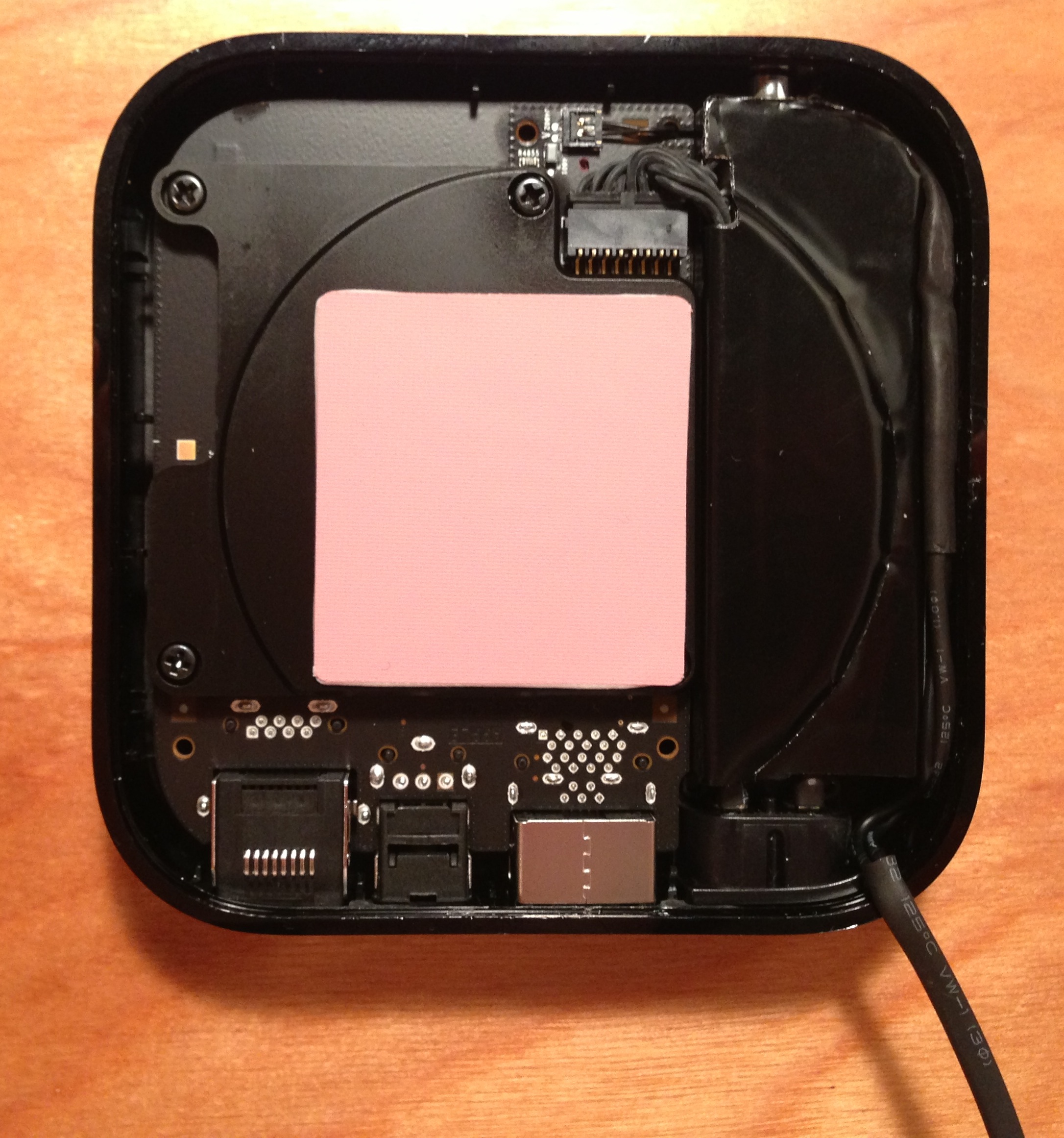
Then I thought about the power led, couldn’t I tie into the wire that powers that led and sense voltage? This solution would involve physically connecting two circuits, which seemed a little out of my comfort zone. I still liked the idea of using the power LED so I came up with using a light sensor, a simple photocell, but the issue of ambient light made me wonder if it would be able to tell the difference reliably. After installing the photocell into the Apple TV unit it turns out hardly any ambient light gets in, and it reliably senses the led no matter what the light conditions outside the case are. It’s not as simple as just sensing on or off, since the light turns off when buttons on the remote are pressed, so I had to code a threshold to keep the system from triggering on and off events erroneously.
1 2 3 4 5 6 7 8 9 10 11 12 13 14 15 16 17 18 19 20 21 22 23 24 25 26 27 28 29 30 31 32 33 34 35 36 37 38 39 40 41 42 43 44 45 | |
So at this point I can reliably sense the state of the Apple TV and fire any action I need to. Now I just needed to give the Arduino some IR capabilities.
Infrared Signaling
All AV equipment, new and old, tends to have an IR sensor, and every IR remote has an IR LED to shoot out pulsed IR light. Remotes are programmed to pulse that IR LED at a very high rate (roughly 38KHz is the standard for most remotes, or 38000 pulses a second). This pulsing is called modulation, and the sensor on the receiver device has to demodulate that signal to decode it and take action, depending on what code was received. Beyond this 38KHz pulsing, IR signals are made up of on/off sequences just like any other binary transmission, but this pulsing happens in the millisecond range. The modulation keeps stray IR light from affecting specific signals coming from IR transmitters.
I wanted to reproduce certain remote control functions such as ‘on’ and ‘input change’ but first I had to deconstruct and record these patterns. I used two methods, capturing the signal from existing remotes, and translating the signal from an online database of remote codes.
Capturing IR Signals from Existing Remotes
The best tutorial for using an Arduino to send and receive IR signals (by far) is this one by Adafruit. They explain modulation/demodulation and provide code to get your Arduino sending and receiving IR in no time. To ‘record’ codes from my current remotes I used this code from Adafruit’s github, with my Uno wired up to an IR sensor like this.
 Image Source: Adafruit Learning System (http://learn.adafruit.com/assets/555)
When you load that code onto your Arduino, open the serial console, point any remote control at it, and press a button, it prints out the pulse/delay sequence you’ll need to reproduce it. Using this method, here is my (shortened) function to send the “power on” signal for my Harman Kardon receiver.
1 2 3 4 5 6 7 8 9 10 11 12 13 | |
You can see from the function above that IR codes are just a series of timed pulses and delays. I used this method to record the “On”, “Off”, and “Input Select Vid 1” codes from my HK remote.
Translating IR Codes from Pronto Hex Format
Since the Apple TV connects to my LG TV I needed to be able to power the TV on and change input, just like the HK Receiver. I planned to use the same method as above, but then realized my LG Remote doesn’t have a specific “On” button, just a power button, and only has one button to cycle through all Inputs. Since I have no reliable way to sense the state of the TV, and which input was currently selected, these 2 remote buttons wouldn’t work for my solution. So I went googling, and learned about “discrete IR codes”. These codes perform one specific function, such as “Power On” and “Select Input Source 1”. The codes are understood by the IR receiver firmware on the TV, but are just not included on the stock TV remote. Luckily, I found a site where people post these discrete codes in a standard format. Here are the discrete power and input select codes for my TV (and I believe most other LG TVs). The format is known as “Pronto Hex” and this article explains how to decode it.
I wrote a ruby script based on the conversion instructions in that article, to convert Pronto Hex format to a set of pulse/delay sets that I could plug into my Arduino program. You can get the code on github here.
Sending IR Signals with Arduino
So at this point I have all the codes I need, but I need a way to send them at my devices. The hardware involved is just a simple IR LED (actually a set of them wired in parallel and placed in front of each shelf of AV equipment). The software extends the code from the Adafruit tutorial. To send the recorded signal I used Adafruit’s IR sending function, which pulses on and off at 38KHz for a number of microseconds. This function is the backbone my project and I want to give full attribution and thanks to Adafruit for doing the dirty work. The code is on github here, and here is the function.
1 2 3 4 5 6 7 8 9 10 11 12 13 14 15 16 17 18 19 20 | |
As of now I use two different formats for IR signals in my Arduino code, the first being a function like sendHKDiscreteOn() above, and the second being a more compressed format from my Pronto Hex conversion script. Here is the LG TV Discrete On code in that format.
1 2 3 4 5 6 7 8 9 10 11 12 13 14 15 16 17 | |
Codes in this format are stored in array constants and I wrote this function to send the code.
1 2 3 4 5 6 7 8 9 10 11 12 13 14 | |
Finally, after a bunch of testing and tweaking, I came up with functions to replay all the codes to control my AV receiver and TV. Here is the one that powers everything on.
1 2 3 4 5 6 7 8 9 10 11 12 13 14 15 16 17 18 19 20 21 22 23 24 | |
Each sequence is sent a few times for some added reliability, and the 10 second delay in the middle is for when the TV is off, as it takes a few seconds to turn on.
I also added a function to set the HDMI select back to the DirecTV box and power everything down. This one will be used when the Apple TV powers off.
1 2 3 4 5 6 7 8 9 10 11 12 | |
Now I have all the software components, time to bring it all together.
Coding it Up
Here’s my pseudocode for the sketch that gets loaded onto my Uno (get the full code listing from my github here).
1 2 3 4 5 6 7 8 9 10 11 12 13 14 15 16 17 18 19 20 21 22 23 24 25 26 27 28 29 30 31 32 33 34 35 36 37 38 39 40 41 42 43 44 45 | |
Now that I have all the code needed to make this work, it’s hardware time.
Building the Circuit
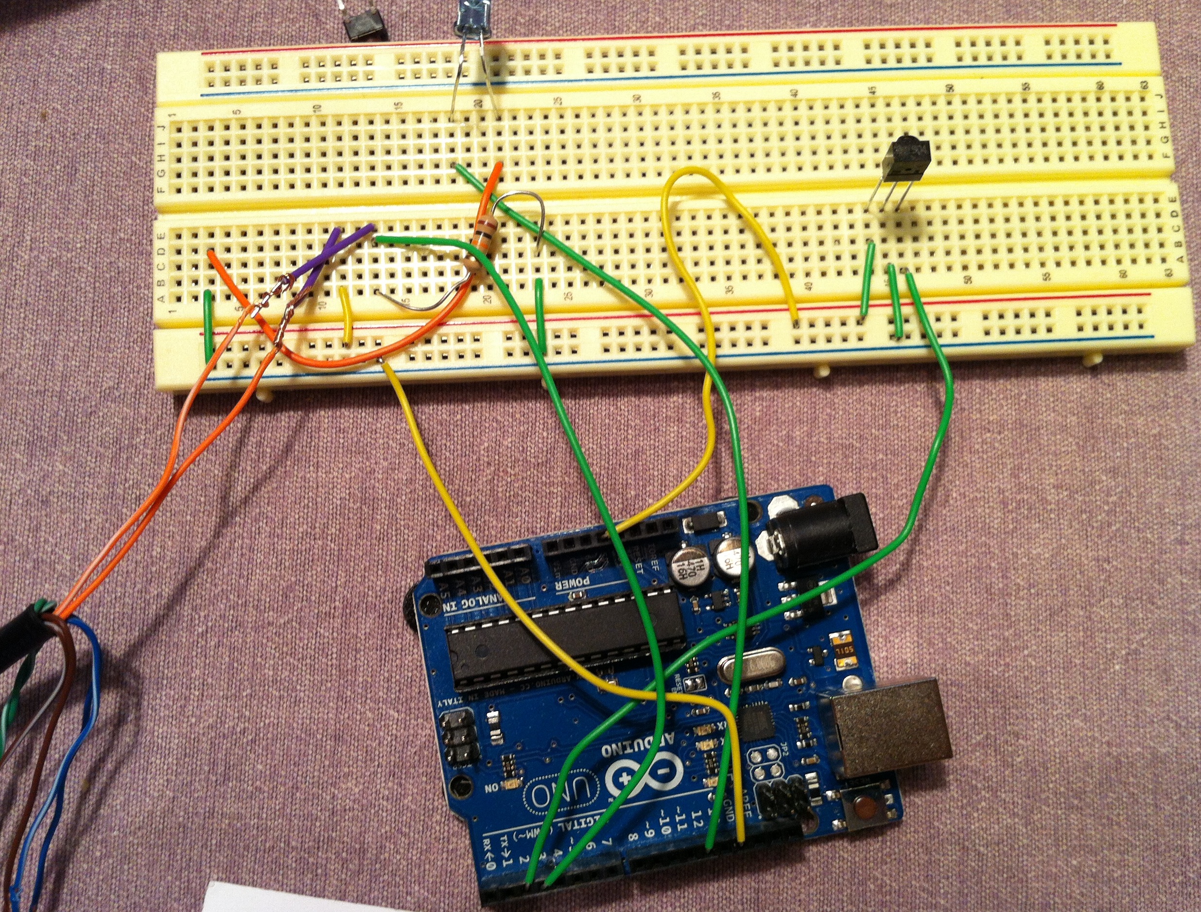
To prove that this all worked, I started with my solder-less breadboard and wired up the circuit like I wanted it. This is the best way to experiment with the Arduino and learn how the analog and digital inputs and outputs work, since you can just mix and match leads and see what happens.
 Then I found this great online circuit schematic editor/simulator circuitlab.com. I drew up my circuit to have a reference, with the Arduino simplified to the inputs/outputs actually used. Here’s the interactive version of my schematic.
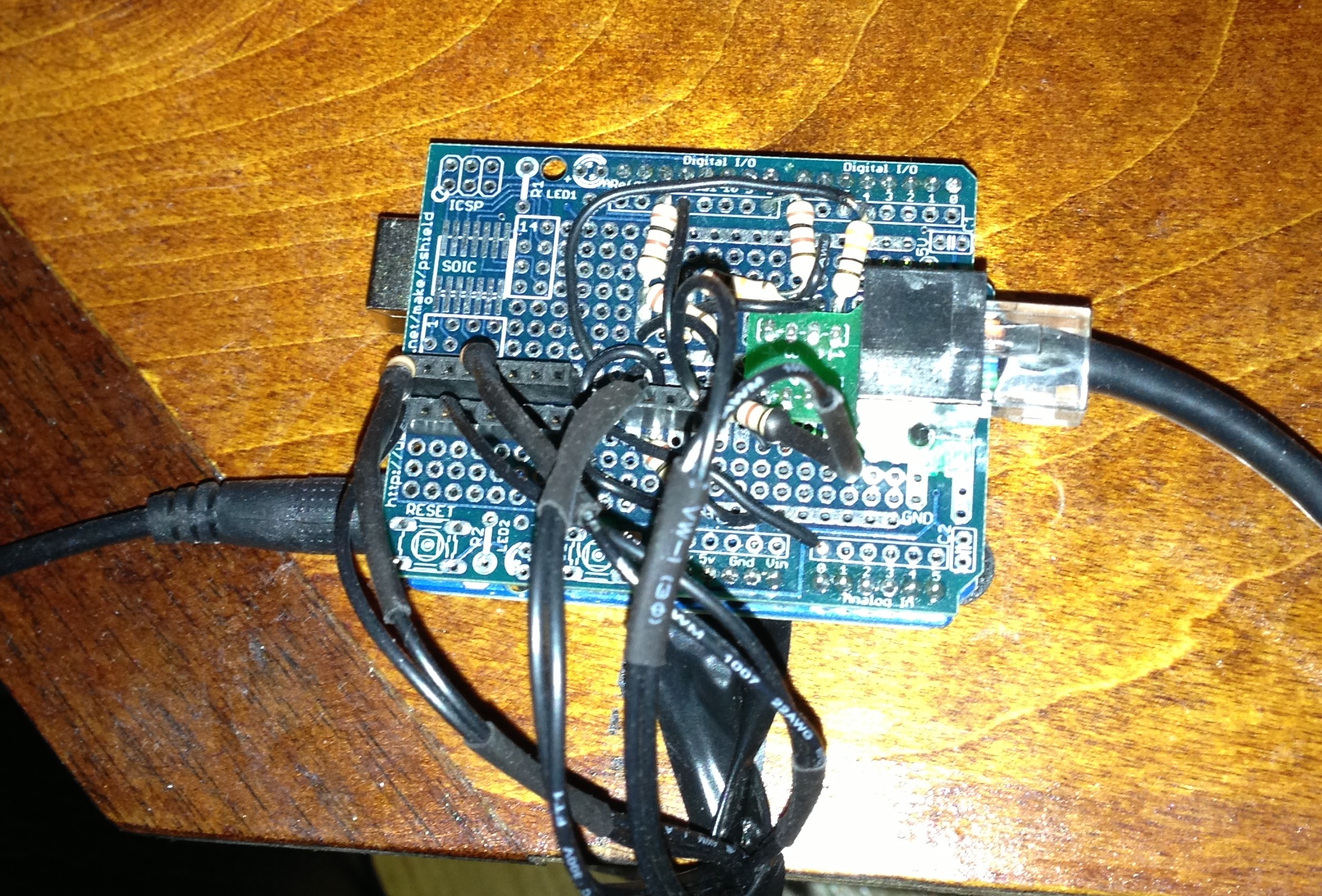
 The Arduino was built to be the core of a project, to which you can add and extend functionality, using the idea of ‘shields’ which basically connect and extend the inputs and outputs of the main board. The best way I found to make a more permanent version of my breadboarded mess of wires, was the protoshield from Adafruit. This board gives you an open grid of conductor-lined holes to solder to, and plugs right into the arduino uno without any modification to the uno.
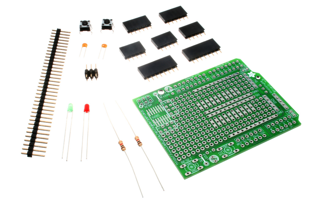 Image Source: http://www.oomlout.co.uk (https://commons.wikimedia.org/wiki/File:Adafruit_Protoshield_Components.jpg)
Here’s a few pics of the board after I finished soldering.
Getting Photocell Sensor into my Apple TV
First, I popped it open, carefully prying the edges on the bottom until the top popped off. The power LED is in the top right of the pics below, and you can see how I routed the light sensor and wires around the edge of the internals.
Installation
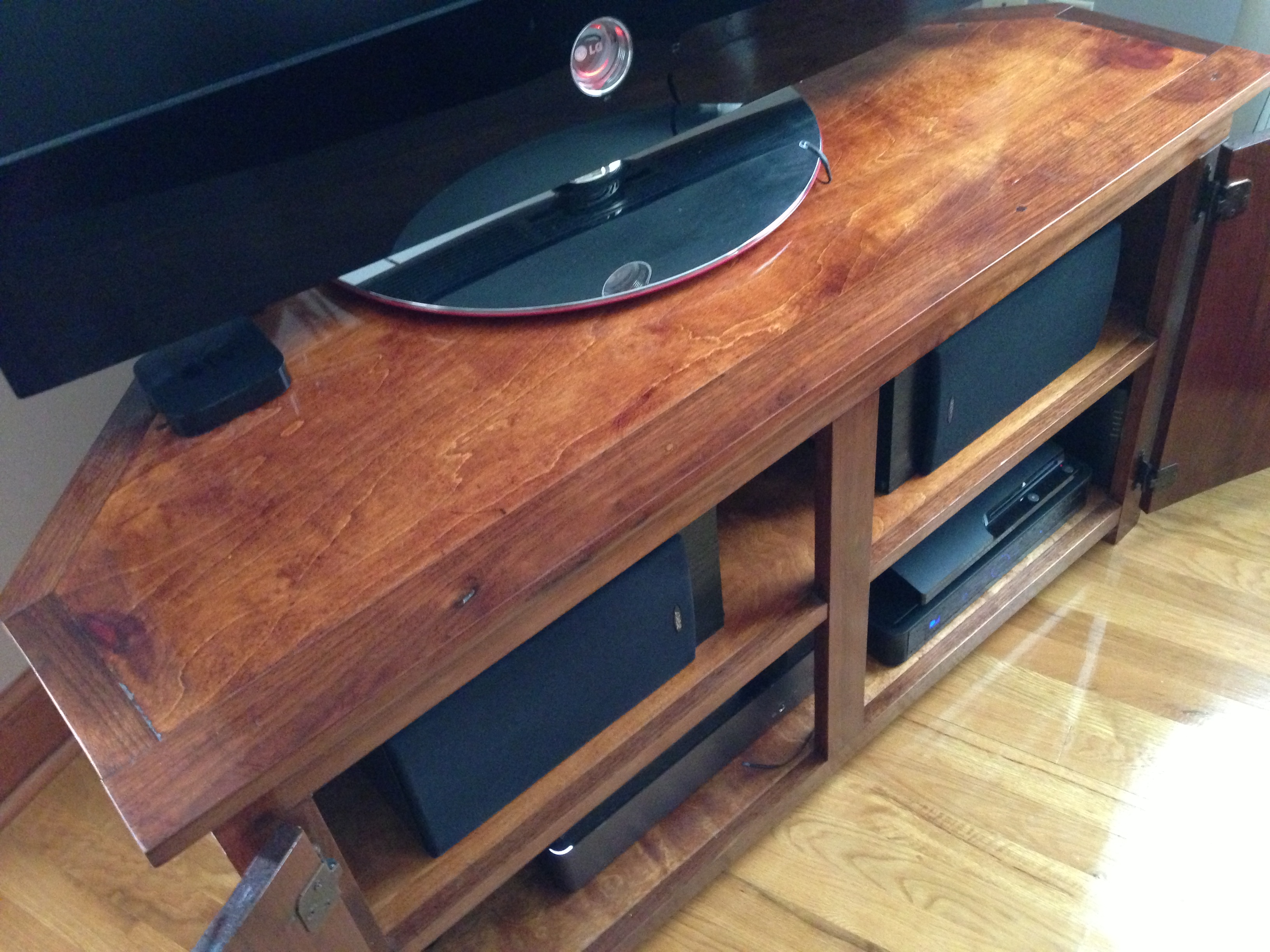
To make sure IR signals made it everywhere, I ran 2 IR LEDs in parallel, connected back to the board by solid copper core wire. One LED sits right in front of the TV, and the Other sits right in front of my AV receiver. I ran a blue LED to a spot near the power button for the TV, and made it pulse when signals are being sent, just to let you know it’s working. Finally, I connected the 2 leads from the AppleTV light sensor, the cat5 cable from the button box (connected to rj45 header on protoshield), and a 9V power adapter, and it was ready to go.
And here’s another pic of the completed board, in all its glory.
Final Thoughts
The project has been running solid for weeks now with no problems, even though it still looks a little prototypy. It took some initial debugging and bugfixing to get the thresholds right, but at this point its passed the ‘wife test’ and it just works. It even turns the input back to our DirecTV signal if the AppleTV is idle for long enough and shuts off.
I have a bunch of ideas to extend the functionality. I’d like to make a web-connected version, with more input events, and on-the-fly IR learning, all of which will minimize the need for all the bulky remotes lying around. If you have any ideas feel free to message me here. I’ll be posting a new write up as soon as I finish V2.
For now, at least, from anywhere in the house, I can sit back, start Airplaying some music, and just bask in the automated goodness as music flows through the house.


